| PSI | EPICS | SLS | SwissFEL | Proscan |

| EPICS at PSI
|
|---|
| Software
|
|---|
| Training
|
|---|
Phone: +41 56 310 5109
Updated: 09.08.2010

Printer friendly version
GENESYS Programmable Power Supply
Introduction
The Genesys™ family of programmable power supplies sets a new standard for flexible, reliable, AC/DC power systems in OEM, Industrial and Laboratory applications.
Now available in more power levels (750W, 1.5kW, 3.3kW, 5kW, 10kW and 15kW) and with available output voltages from 7.5 to 600V, and current up to 1,000A.
Active PFC, and universal input head a long list of standard features.
| 1U High | 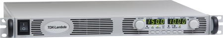 |
In all there are 12 new variants in the Genesys™ 750 line-up offering a range of constant current outputs up to 100A at 6V and constant voltage outputs up to 600V at 1.25A. An MTBF greater than 100,000 hours makes it ideal for a diverse range of markets including industrial, telecoms, military and medical. Applications range from flight simulators, radar systems and automotive parts testing to process control, automatic test equipment, ion implantation, semiconductor burn-in and lasers.
| 2U High | 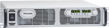 |
The power supply’s user-friendly front panel provides highly accurate control through digital encoders selectable for fine (6 turns) or coarse (30 turns) adjustment and four-digit LED voltage and current meters. Overvoltage protection (OVP), undervoltage lockout (UVL) and current foldback are all adjustable and their set values can be displayed on the front panel. Foldback may be set to latch output off if desired.
A Safe Start feature allows the user to choose whether Genesys™ returns to previous settings after power off, or returns to zero (safe) output awaiting user instructions. The power supply’s Last Setting Memory retains settings of output voltage and current, remote or local mode, OVP and UVL, foldback, baud rate and start up mode.
The Genesys™ incorporates a standard, embedded 16-bit RS232/RS485 digital interface, through which up to 31 power supplies can be controlled in daisy chain over the RS485 line. Analogue remote programming is user-selectable 0-5V or 0-10V via DIP switches located on the rear panel of the unit. In test systems up to four power supplies may be connected in parallel with one-wire current share control, or two may be connected in series.
| 3U High | 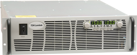 |
Optional interfaces include a digital interface that is both IEEE488.2 and SCPI compliant. Labview drivers are also available. Isolated analogue programming options include a choice of 0-5V and 0-10V or 4-20mA control.
This EPICS Application supports the RS232/RS485 serial interface of the Lambda GENESYS power supply.
System Requirements
The current version of GENESYS has been tested against the following software:-
- StreamDevice Version 2.0
- EPICS Version 3.14.7
- LINUX Version 2.4.18
Configuration and Setup
Source code is available by checking out the GENESYS module from the CVS repository
The templates available for these power supplies:-
- GENESYS-1U.template
- GENESYS-2U.template
The 2U template is used for both 2U and 3U power supplies.
The simplest method to obtain the correct version of the template file is to use the "getCommons" program. This requires a file called COMMON_FILES in your development directory.
The COMMON_FILES file has the following structure:
###################################################### File name CVS Location CVS Tag
####################################################
GENESYS-1U.template GENESYS HEAD
Create a substitution file and define the macro parameters needed
Eighteen macro names have been defined for both templates:-
| Macroname | Typical Values | Description |
| IOC | TEST-VME-01 | The name of the IOC the PSU is connected to. |
| MODULE | GENESYS | Module name (usually the CVS module name) |
| SCONF | GENESYS_psu | Protocol configuration file name in the cfg directory |
| SERIAL | PSU | name of the serial connection defined in the script. See the notes in the example substitution file |
| GENADR | 6 | This is the address of the PSU we are controlling. The default value is 6 |
| NAME | PSU-01 | Used to create the PV names. See the notes in the example substitution file |
| COMSPD | 19200 | Baud Speed of the Communications link. See the notes in the example startup.script file |
| COMDEV | /dev/ttyS4 | Communication link device name See the notes in the example startup.script file |
| DRVHV | 600 | This value depends on the PSU model we are controlling See the notes in the example substitution file |
| HOPRV | 600 | This value depends on the PSU model we are controlling See the notes in the example substitution file |
| IPRDRVH | 1.300 | This value depends on the PSU model we are controlling See the notes in the example substitution file |
| IPRHOPR | 1.300 | This value depends on the PSU model we are controlling See the notes in the example substitution file |
| IPRPREC | 3 | This value depends on the PSU model we are controlling See the notes in the example substitution file |
| OVPDRVH | 660 | This value depends on the PSU model we are controlling See the notes in the example substitution file |
| OVPDRVL | 5.0 | This value depends on the PSU model we are controlling See the notes in the example substitution file |
| UVLDRVH | 570 | This value depends on the PSU model we are controlling See the notes in the example substitution file |
| UVLDRVL | 0 | This value depends on the PSU model we are controlling See the notes in the example substitution file |
| SIMM | YES | Default is NO, for Simulation use YES The PV used will be named $(IOC):$(MODULE)-TST and is derived from the above macro names |
A copy of the protocol file GENESYS_psu is needed in your cfg directory. Edit this file to accurately reflect the correct values for your system.
A copy of the startup script startup.script is needed in your working directory. Edit this file to accurately reflect the correct values for your system.
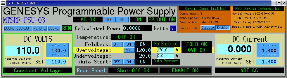
Graphical Interface
An Engineering GUIs are used to display and control the operational parameters of the power supply.
1U Power Supply
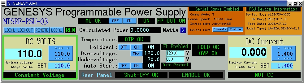
The GUI for the 1U version of the power supply is started with the command:-
medm -macro "NAME=XXXXX-XXX" -x G_GENESYS-1U.adl
the NAME macro is the same as the $(NAME) defined in the template file.
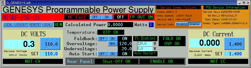
When the GENESYS power supply is switched off the GUI displays the status above ("AC FAIL", "Serial Coms failure" and "OFF" is invalid in white).
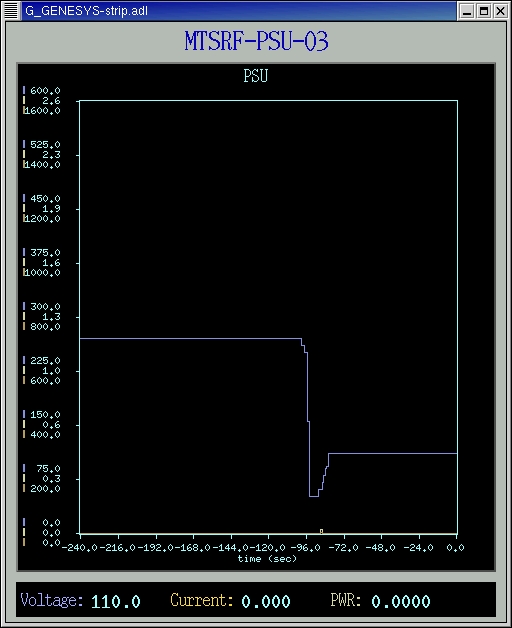
A stripchart display is available to show the values of voltage, current and power supplied by the GENESYS power supply. This display is obtained by the "S" button on the main display.
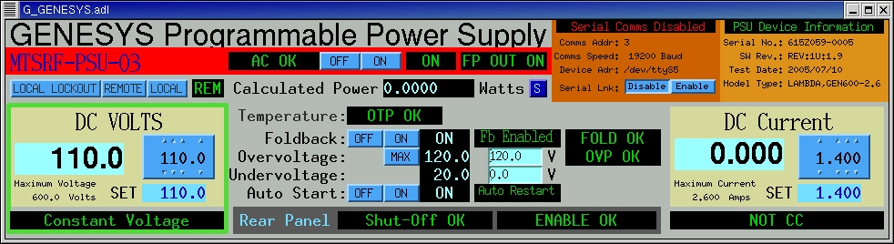
It is possible to disable the serial link communications for each GENESYS PSU on the serial line. This is done with the Enable/Disable button on the main display.
2U and 3U Power Supplies
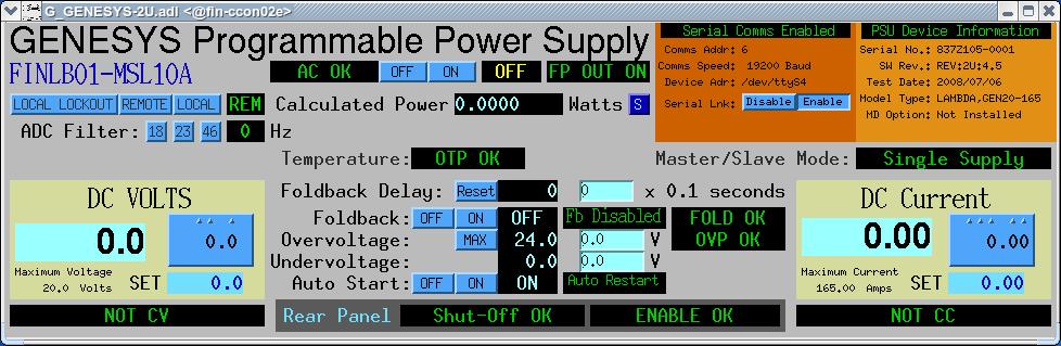
The GUI for the 2U and 3U versions of the power supply is started with the command:-
medm -macro "NAME=XXXXX-XXX" -x G_GENESYS-2U.adl
the NAME macro is the same as the $(NAME) defined in the template file.
Alarms
Alarms can be defined in the alarm handler package, an example file is supplied in the App/config/alh directory.
| Macroname | Description |
| $(NAME):FLT-ACF | Mains power AC Fail has occurred. |
| $(NAME):FLT-OTP | PSU Over Temperature Shutdown. |
| $(NAME):FLT-FOLD | PSU Foldback Shutdown. |
| $(NAME):FLT-OVP | PSU Over Voltage Shutdown. |
| $(NAME):FLT-SO | PSU Rear Panel Shutoff. |
| $(NAME):FLT-ENA | PSU Rear Panel Enable problem. |
| $(NAME):COMSTAT | Serial Communications link disabled. |
GENESYS Unit System Testing
Testing of the GENESYS software is described in a separate link Unit testing of the GENESYS system.
Known Problems
The GENESYS PSU serial connection can easily be daisy chained from one PSU to a second or third PSU. The software ( Version TAG GENESYS_1_X ) has been tested in this configuration. During normal use the problem manifests itself by reporting "lock timeouts" on the error message stream, and the user will see on the GUI the "Serial Comms Failure" messages being displayed in red.
The current work around is to configure only ONE GENESYS Power Supply Unit per serial connection. This problem will be addressed in the next version of the software.
Author: Dennis Armstrong Phone: +41 56 310 5109 Email: dennis.armstrong@psi.ch Updated: 09.08.2010 Source: /afs/psi.ch/project/epics/webhosting/software/streamdevice/genesys/GENESYS.php